How do you check/analyze routing congestion?

We can analyse Congestion hotspot at different stage:

  • eGR hotspot at preCTS or post-CTS opt - the step just before routing
  • NR-GR hotspot before detail routing

After detail routing we check for DRCs and Shorts.

Congestion Maps: Similar to placement congestion analysis, PnR tools generate visual congestion maps based on eGR or NR-GR

Overflow Reports: Tools provide reports listing GCells with overflow (demand > supply) and quantifying the overflow percentage or the number of overflowing tracks. This helps pinpoint the most problematic areas.
Share:

How do you fix setup violations? What if upsizing/layer change isn't possible?

o We need to reduce cell delay or Net delay or use more skew – can use various methods for each.

  • o Reduce Cell Delay:

  • oCell Sizing (Upsizing): Increase drive strength of cells on the critical path. (Effective for small to moderate violations).

  • oVT Swapping (Lowering Vt): Swap cells to faster, lower-Vt variants (HVT->SVT->LVT). (Effective, but increases leakage).

  • oReduce amount of buffering if excessive bufs are added.

  • o Reduce Net Delay:

Share:

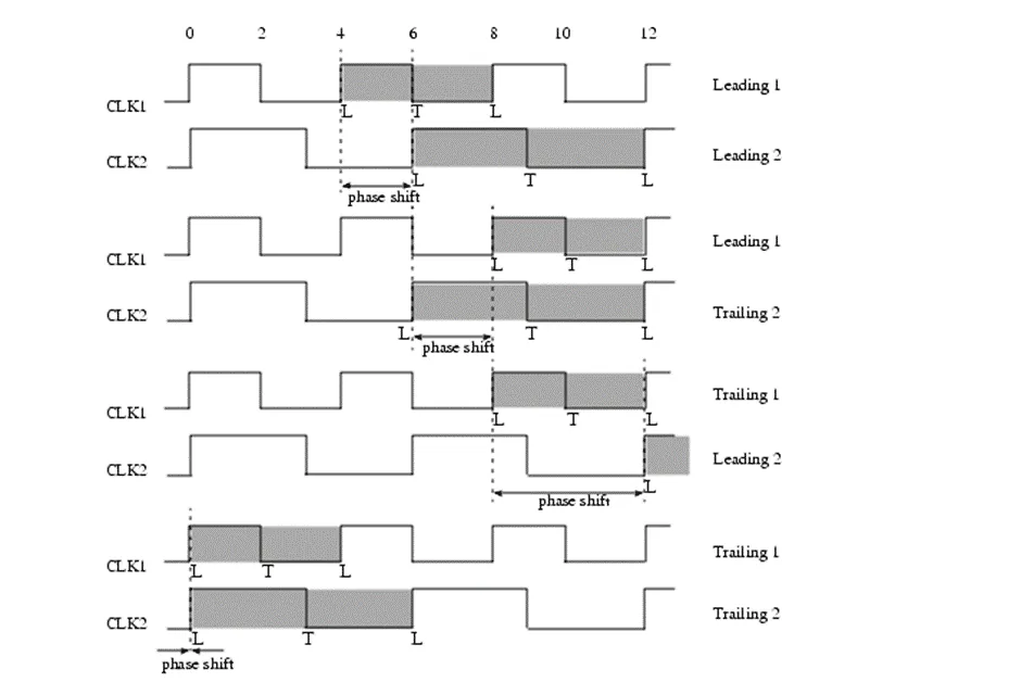
How do you handle timing when the capture flop frequency is twice the launch flop frequency?

oTools calculate phase shift as explained below. If same clock drives launch and capture, phase shift is equal to one clock period.

  • Timing Analysis Approach:
  • Phase shift = time period of capture clock in this case.
  • It may need MCP if required.

Share:

How to analyze a timing report?

oPath Summary:

Startpoint: Where the path begins (input port or flop clock pin).

Endpoint: Where the path ends (output port or flop data input pin).

Path Group:

Path Type: Setup, Hold, Recovery, Removal, Min Pulse Width, etc.

Slack:

Data Arrival Time Path: Details the delay contribution of each element along the data path:

Clock Network Delay (Launch): Latency from clock source to launch flop clock pin (relevant post-CTS).

Clock-to-Q Delay: Delay through the launch flop.

Share:

How to check and fix IR drop during routing?

oWe can run IR aware full flow

  • IR aware placement : Spread high power density hotspots to reduce IR drop. Tools settings using setPlaceMode. This is useful even during routing as during optimization tool adds buf/inv and updates placement increamentally.
  • CCopt/SkewClock: skew the clock to minimize peak current
  • Reinforce_pg: Auto RPG: Loacl PG stripe/via addition in hotspot area. (separate utility from cadence. Needs voltus IR setup as input.
  • Fill: Maximize PG hookup at signoff stage.
  • https://support.cadence.com/apex/ArticleAttachmentPortal?id=a1O3w000009foP9EAI&pageName=ArticleContent

In general routers are now performs rudimentary current density estimation on wires and handles IR/RM.

Share:

How to fix congestion at routing stage?

Congestion reported by eGR fafter place or CTS is more as, eGR detours less to avoid congestion, it helps finding congestion before hand instead of detouring nets. Fixing congestion after route is usually difficult and it should be addressed by placement stage.

Route Effort: Increase the effort level of the detailed router (setRouteMode -detEffort high). The tool will spend more time trying alternative paths or rip-up and reroute techniques.

Congestion-Driven Routing:

Share: