What are sync flops ? How will you model them? what all are setup and hold check required?

oThey are used when signal crosses asynchronous clock domains.

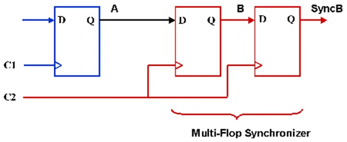
Sync Flop added between two flops operating on asynchronous clocks to avoid metastability.

The main responsibility of a synchronizer is to allow sufficient time such that any meta-sable output can settle down to a stable value in the destination clock domain.

Generally 2 stage synchronizer is sufficient to remove all likely meta-stability.

Sync flops operating on destination clock domain.
Share:

What are the things needed to be taken from sub-blocks to the main block? How do you take logical information of sub-blocks?

oLogical View (Timing Model - .lib or .db**):**

  • Provides the timing characteristics of the sub-block’s input/output pins (setup/hold times, clock-to-output delays, internal path delays)
  • Defines cell functions (if it’s a soft macro with standard cells) or overall block function.
  • Needed for top-level STA and synthesis (if the sub-block is a soft/firm macro).
  • Physical View (Abstract Layout Model - LEF):
  • .lef file of Hard Macro or soft macro/sub blocks.
  • Defines the physical footprint (width, height), pin locations, pin layers, metal blockages (OBS layers) within the sub-block.
  • Constraint View (SDC partial/interface):
  • Interface timing constraints for the sub-block’s pins (e.g., specific false paths or multicycle paths internal to the IP that the top level should be aware of, or constraints on its I/O pins).
  • UPF and GDS for merging at last to get complete top-level GDS.

Share:

What checks can be done using redhawk?

oStatic IR Drop Analysis: Calculates the average voltage drop across the PDN based on average current consumption (leakage + average switching).

Dynamic IR Drop Analysis (Voltage Droop): Simulates transient voltage drops based on switching activity.

Power/Ground EM Analysis: Checks for electromigration violations (average, RMS, peak current density) on the VDD and VSS network wires and vias based on calculated currents.

Signal EM Analysis: Checks for EM violations on signal interconnects, which is increasingly important at advanced nodes.

Share:

What flow is followed for ECO / timing closure?

o After post route database has acceptable timing and drc numbers, we start ECO phase.

  • If power recovery is reuired, start with power recovery where tool downsize or VT swap cells in timing paths with positive slack to save power.
  • Then start fixing drv/setup/hold timing. Generate ECO file manually or from STA tool, on single session or DMSA environment. Apply ECO on post route database in PNR tool, save design and dump outputs and rerun timing, Physical verification like DRC, LVS, Antenna, etc. IR EM analysis can be done.
  • Iterate ECO cycles till timing is clean. Once all ECOs are implemented and locally verified, run full signoff checks (STA, DRC, LVS, EM/IR) on the final ECOed database.
  • ECO Flow: https://teamvlsi.com/2021/02/eco-flow-in-physical-design.html

Share:

What if cells are low drive strength and no space for decaps to fix IR?

We have dynamic IR issue where specific location; cells are already low drive strength and no space to add decaps. We can still reduce IR by following ways:

  • Improve PDN: add extra stripes or vias in that region if possible.
  • Change in switching window: Analyze the switching activity. If many cells (even low-drive ones) in the area switch simultaneously causing the droop, try to introduce small timing delays on non-critical paths feeding into this region to slightly spread out the switching events over time. This reduces the peak current demand at any single instant.
  • VT Swapping (Higher Vt): if there are some LVT cells contributing to the switching current in the region, swapping them to higher Vt (SVT/HVT)
  • Re-evaluate Floorplan/Placement:

Share:

What inputs are needed at CTS for sub-blocks?

o The top-level SDC must correctly define the clocks reaching the input clock ports of the sub-blocks.

If a sub-block generates clocks that are used by other blocks or the top level, these generated clocks must also be properly defined (e.g., using create_generated_clock sourced from a sub-block’s output pin).

  • Sub-Block Timing Model (.lib**) and Physical Abstract (LEF):**
  • CTS Exceptions for Sub-Block Pins:

Share: