STA Interview Questions

Have you seen setup fails in ATPG TEST mode?

oScan shift runs at lower frequency but scan capture runs at function or near functional frequency. In capture mode we can see setup violations.

  • ATPG patterns activate paths that might not be the most critical during normal functional operation but become critical under specific test stimuli. These paths might not have received sufficient optimization focus during PnR if only functional mode was prioritized.
  • False Paths in Functional Mode: Paths that were correctly defined as false paths during functional mode might become active during certain ATPG patterns (especially if set_case_analysis for test mode enables them).
Hold timing is checked in which mode (Max or Min)? Why?

oHold timing is checked using Minimum (Min) path delays. This is often referred to as Min Timing Analysis or Best-Case Analysis.

  • Hold Violation Condition: A hold violation occurs if the new data launched by the launch flop arrives at the capture flop before the capture flop has had enough time to reliably capture the previous data from the same clock edge. In other words, the data path is too fast relative to the clock path.
  • Worst-Case for Hold: The worst-case scenario for a hold violation happens when:
  • The data path is at its fastest possible speed (minimum delay).
  • The launch clock path is at its fastest possible speed (minimum latency).
  • The capture clock path is at its slowest possible speed (maximum latency).
  • Therefore, hold checks use minimum path delays (Min timing mode) to find the scenario where data arrives earliest, posing the greatest risk of violating the hold requirement.

How are TEST mode & FUNC mode defined and constrained?

oDefining Modes: Different operating modes are : Functional mode - FUNC and test Modes: Scan Shift, Scan Capture, BIST

  • Defined in MCMM setup with create_constraint_mode command and given separate SDC of each mode.
  • Separate SDC Files: Each SDC file contains the appropriate set_case_analysis settings, relevant clock definitions (test clocks might differ from functional clocks), and potentially different timing exceptions or I/O delays specific to that mode.
  • Mode-Specific Constraints within one SDC: Less commonly, complex logic within a single SDC file might be used to apply constraints conditionally, but separate SDCs or set_case_analysis are standard.

Checking Simultaneously (MMMC):

How do you fix setup violations? What if upsizing/layer change isn't possible?

o We need to reduce cell delay or Net delay or use more skew – can use various methods for each.

  • o Reduce Cell Delay:

  • oCell Sizing (Upsizing): Increase drive strength of cells on the critical path. (Effective for small to moderate violations).

  • oVT Swapping (Lowering Vt): Swap cells to faster, lower-Vt variants (HVT->SVT->LVT). (Effective, but increases leakage).

  • oReduce amount of buffering if excessive bufs are added.

  • o Reduce Net Delay:

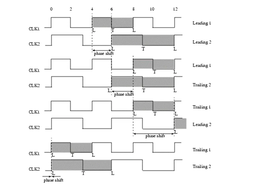
How do you handle timing when the capture flop frequency is twice the launch flop frequency?

oTools calculate phase shift as explained below. If same clock drives launch and capture, phase shift is equal to one clock period.

  • Timing Analysis Approach:
  • Phase shift = time period of capture clock in this case.
  • It may need MCP if required.

How to analyze a timing report?

oPath Summary:

Startpoint: Where the path begins (input port or flop clock pin).

Endpoint: Where the path ends (output port or flop data input pin).

Path Group:

Path Type: Setup, Hold, Recovery, Removal, Min Pulse Width, etc.

Slack:

Data Arrival Time Path: Details the delay contribution of each element along the data path:

Clock Network Delay (Launch): Latency from clock source to launch flop clock pin (relevant post-CTS).

Clock-to-Q Delay: Delay through the launch flop.